Wednesday 29 February 2012

Modelling the Character

Tutorial link that helped to me to create my character.

To create my character I firstly started by creating a cube which I then split into segments to allow designated areas for the arms legs and head. This cube would form the torso of the body.


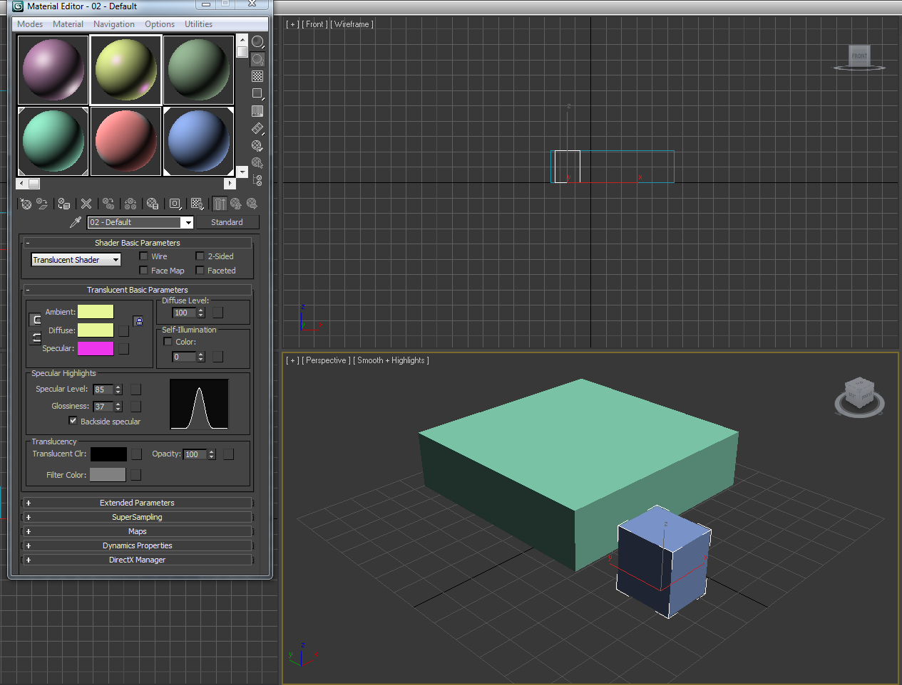
To create the extended parts from the torso I created the object into an editable poly. Editable Poly is an editable object with five sub-object levels: vertex, edge, border, polygon, and element. Its usage is similar to that of an editable mesh object, with controls for manipulating an object as a polygon mesh at various sub-object levels. Rather than triangular faces, however, the poly object's faces are polygons with any number of vertices.
 I selected the face of each segment and right clicked. This allowed me to either extrude or bevel. I used bevel mainly for areas such as the head. This allowed me to increase the width at certain areas as well as decrease the width at thinner areas. This gave the body a realistic shape.
To create the arms I decided to make them on a separate file and attach them on. The reason for this was so they were the correct shape and in the correct angle to be hanging from the parachute. I simply made the arms by using the rectangle tool and the bevelling tool to shape the arms. For the fingers I simply cut the hand into more segments to create the fingers in a gripped position.

The problems I faced whilst creating my character were I found the extrude tool quite difficult to use for the legs. I feel it was hard to create the leg structure using the basic tools.However I was pleased with the arms i had created,once these were complete I cloned and flipped them into position. 


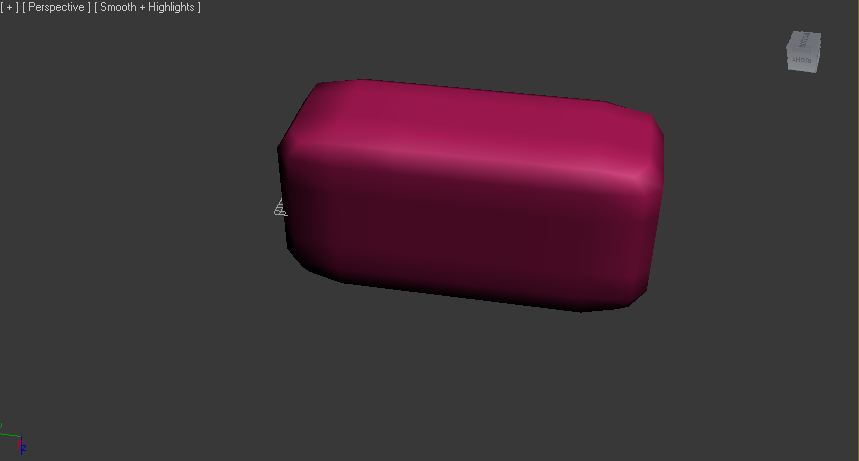
Once the human was complete I applied the turbosmooth modifier.
TurboSmooth lets you subdivide the geometry while interpolating the angles of new faces at corners and edges, and apply a single smoothing group to all faces in the object. The effect of TurboSmooth is to round over corners and edges as if they had been filed or planed smooth. Use TurboSmooth parameters to control the size and number of new faces, and how they affect the surface of the object.

Modelling the Parachute

This summary is not available. Please click here to view the post.

Shaders

Anastropic
This is a very useful shader for a variety of real-world objects, such as hair, glass, or brushed metal. If the specular highlight on an object should come together in a narrow beam, instead of the broad circle that the Blinn/Phong shaders generate, then the Anisotropic shader is what you need.

Blinn
Blinn shader is the default shader. It renders simple circular highlights and smoothes adjacent faces. The Blinn shader includes color swatches for setting Ambient, Diffuse, Specular, and Self-Illumination colors.

Metal
This was in use until the Anastropic shader was introduced, it is more simple in the way it works, there is a dimple in the specular graph, which means that the shader is useful for dull metal materials such as brushed stainless steel.


Muli-layer
This is very good for metalic objects, particularly cars, as it has two layers of specularity. You can also change the colours of the specular layer to add subtle tones.


Orin-Nayer-Blinn
This is much softer in tone than Blinn and produces a very soft feel to the material. It is ideal for organic materials such as skin, velvet, as it slightly absorbs light.


Phong
This is one of the original shaders and is not really used anymore. Gives a plastic feel to a material.


Strauss
This shader is best used for more advanced modeling of metallic surfaces. Its specular highlights can be modified, but it doesn’t quite look like the Metal shader.

Translucent

This is a fun shader - and can be used to produce psychodelic influences on the material, glowing effects etc. It offers translucency, and opacity plus filter colour.


Rendering

Steps to Rendering
1.Click on Render in the top tool bar,( icon) teapot

2.Output size – check 640 X 480

3.Scroll down to Render output > Files, and select the area you wish to save your file.

4.Save as type BMP or JPEG, and press SAVE.

I5.n the Render Scene dialogue click on RENDER.

Leaf Tutorial

In this tutorial we created a leaf using clever material mappings on 3ds max.Firstly we opened the leaf in photoshop.Using the magic wand tool we selected the leaf.We then added a new layer and filled the background to black.
once the black layer is covering the edges of the leaf make a new layer below it and fill it with white.


Once this has been saved ,create a simple plane on 3ds max.Found in Primitive shapes.You will need to make sure you increase the number of length and width segments to around 30 to enable you to bend and shape the leaf later.
By pressing ‘m’ on the keyboard it will bring up the material editor and then choose the first available empty material.
Click on the small grey square next to the diffuse colour and then double click on Bitmap and choose the leafLARGE.jpg image.
Click Go to Parent button in the material editor.
Scroll down and locate the Maps tab from here click on ‘None’ in the box next to ‘Opacity’ Then double click on Bitmap like before. This time select the black and white image we made earlier.
Look back at the Maps tab of the parent material and click the ‘None’ box next to the ‘bump’ option. Then like before, double click on ‘bitmap’ and then select the original leaf image.

Click on the plane and then add the ‘edit poly’ modifier.Selecting the vertex and then with soft selection you can shape the leaf.


Monday 27 February 2012

Da Vinci Inventions

Da Vinci Inventions
Da Vinci’s helicopter measured more than 15 feet in diameter and was made from reed, linen and wire. It was to be powered by four men standing on a central platform turning cranks to rotate the shaft. With enough rotation, da Vinci believed the invention would lift off the ground. Unfortunately, due to weight constrictions, modern scientists do not believe da Vinci’s invention would have been able to take flight.
Leonardo da Vinci made the first real studies of flight in the 1480's. He had over 100 drawings that illustrated his theories on flight.
The Ornithopter flying machine was never actually created. It was a design that Leonardo da Vinci created to show how man could fly. The modern day helicopter is based on this concept.
A typical cannon of Da Vinci's age was cast iron or bronze, had a short barrel, a short range and fired cannonballs which fitted very approximately.He wanted to increase the rate of firing weapons and so designed machines with multiple cannons, so they could be fired successively or all together.


Tank. Designed around 1483-85. There's a sighting turret on top, the skin is supposed to be covered with metal plates, and the vehicle moves by way of eight men operating a complex system of gears (Leonardo thought about using horses for movement, but figured they'd be too scared by the explosions).
I chose the parachute as I thought it would be interesting to animatate flying over the 15th century Italian city scape.On research to Leanardo da Vinci ,I found many usefull books to get an insight into the mind and workings of Da vinci.


Leonardo is also renowned as a scientist, engineer and inventor. The areas of his scientific study included aeronautics, anatomy, astronomy, botany, cartography, civil engineering, chemistry, geology, geometry, hydrodynamics, mathematics, mechanical engineering, optics, physics, pyrotechnics and zoology.


The three models I will be creating is a person,a parachute and a city scape.
Here is an excellent tutorial i found for creating humans in 3ds max.

Lofting tool tutorial


Lighting tools

Lighting tools
There are five types of lights in 3D Studio Max:


  • Ambient light
  • Omni lights that cast unfocused light in all directions
  • Directional lights that cast parallel beams of light in one direction
  • Target spotlights that cast a focused beam of light towards a target
  • Free spotlights that cast a focused beam of light in a direction.


Make a small scene, click and drag a plane in the perspective viewport and place assorted standard and extended primitives on that plane, so that you can test out the different lights.
Go to the Create panel, and click on the small lighting symbol. Where you can see Photometric, click on the side arrow and select Standard.
In the Front viewport click and drag a target spot.
In order to see your lighting update it is a good idea to change one of the viewports to Perspective view – Active Shade.
Target Spotlights are very useful for mood lighting, freetarget spots can be used for car headlamps, streetlamps etc. A spotlight illuminates an area within a cone, similar to a stage light. Target Spotlights point at a target that you aim at, whereas few spotlights are targetless, so they can be moved easily. You can align a target light to a path and animate it if you wanted to.With your target spotlight highlighted, go to the modify panel, and it will reveal a target spotlight rollout.


This screen shot is target spot lighting .
Spot Light
A spotlight casts a focused beam of light like a flashlight, a follow spot in a theater, or a headlight. The only difference between a spotlight and a directional light is that the directional light is composed of all parallel light beams, while the spotlight’s beams all emanate from one point. A target spotlight uses a target object to aim the camera.


Tuesday 21 February 2012

Advancing techniques

Pro Booleans for 3ds Max is a reliable, production-proven modeling tool that lets you quickly model inorganic shapes. Integrate and automate Pro Booleans functionality into your production pipeline with robust MAXScript support.

Pro Booleans Advantages:

  • Better Quality Mesh – fewer small edges and skinny triangles.
  • Smaller Polygon Count – minimize vertices and faces.
  • Easier and Faster To Use – unlimited number of objects per Boolean operation.
  • Cleaner-looking Mesh – co-planar edges remain hidden.


This screen shot is a practice at using the pro boolean tool.The object in the end was to be a peice of cheese.i found the tool easy to use and it creates some interesting shapes.


MAX comes with a wide variety of textures included, but they aren't perfect, and knowing how to fix them and add your own materials and material libraries is vital to successful projects.Materials in MAX are made up of several different maps, each of which can be edited and tweaked to perfect your materials.Bump maps apply texture to a material by using the light and dark values of the bump map image. Dark areas of the image will be rendered as recessed, while light areas will be raised.


Lathe toolI created this by using the line tool .I drew the basic profile outline of the glass and closed the spline after.Lathe is a feature that enables you to create a 3D object by rotating a shape or a line around an axis.By using a modifier i was able to fill the shape to 3D.


Bump Tool
Bump maps apply texture to a material by using the light and dark values of the bump map image. Dark areas of the image will be rendered as recessed, while light areas will be raised.
In order to make my own material I used Photoshop.Making a new file, approx 3cm x 3cm ,Saving as a bitmap.It can then be imported in on material editor.


 Materials can be applied by dragging and dropping them to the shape.


'At the top of the default Material Editor window is a menu of options including Material, Navigation, Options, and Utilities. The menu commands found in these menus perform the same functions as the toolbar buttons, but the menus are often easier to find than the buttons with which you are unfamiliar. '

'Six sample slots that display a preview of some available materials come below the menus. Surrounding these slots are button icons for controlling the appearance of these sample slots and interacting with materials.'www.expertrating.com


 This is a screen shot of experimenting with different colours and shades in material editor.i found this task quite easy,it was interesting to see the types of effects you can create within the software.


High shine,this is created by changing the specular level on material editor.


Importing a picture is as a bit map and dragging it to the object.

     To create the torus knot it was selected from extended primitives. Opening the Material
editor. Pick an Anastropic shader as this is ideal for metal materials. Check on the diffuse button and change the colour to a dark blue. Make sure that you have a high specular level approx 60 and a high anastrophy approx 80.
     Reflection > None.In the Material library add in your image. This will now add the image to the reflective map channel.you add it to the torus knot you drag and drop.


The Inventions

The invention iIhave decided to create will the parachute.I have chosen this as I think it will be a challenge for me and I also think it will be enjoyable to animate.
Leonardo's parachute consists of sealed linen cloth held open by a pyramid of wooden poles. In his notebook he remarks that with such a device anyone can jump from any height without injury.

Skydiver Adrian Nicholas tested Leonardo's design, jumping from a hot-air balloon at 3000 metres. He found the ride to be smoother than the modern parachute. However weighing over 90 kg, it put the parachutist in danger of injury on landing.
Like many of da Vinci’s ideas, the invention was never actually built or tested by Leonardo himself. But, in 2000, daredevil Adrian Nichols constructed a prototype based on da Vinci’s design and tested it. Despite skepticism from experts, da Vinci’s design worked as intended and Nichols even noted that it had a smoother ride than the modern parachute.
Da Vinci's parachute flies
By BBC News Online's Dr Damian CarringtonLeonardo Da Vinci was proved right on Monday, over 500 years after he sketched the design for the first parachute.
A British man, Adrian Nicholas, dropped from a hot air balloon 3,000 metres (10,000 feet) above the ground, after ignoring expert advice that the canvas and wood contraption would not fly.
Attempts to fully test the parachute in the UK earlier this year failed due problems of wind and safety near populated areas - it weighs a hefty 85 kilograms (187 pounds).
But in the wide open spaces of Mpumalanga, South Africa, Mr Nicholas safely floated down, saying the ride was smoother than with modern parachutes.

Wednesday 8 February 2012

About Da Vinci

A painter, a sculptor, an architect and an engineer, Leonardo Da Vinci's numerous skills have earned him the title of renaissance master. Da Vinci's fascination with science and his in-depth study of human anatomy aided him in mastering the realist art form. While Leonardo's counterparts were known to create static figures in their works, Leonardo always tried to incorporate movement and expression into his own paintings. All the personages in his works are painted with great accuracy and detail that it is sometimes said that Da Vinci painted from the bones outward.
Having lived until the age of 67, Leonardo experienced a very long career that was filled with times during which the painter was celebrated, but at times he was also humiliated and cast away.
Leonardo's fascination with machines probably began during his boyhood. Some of his earliest sketches clearly show how various machine parts worked. As an apprentice in the studio of the artist Verrocchio, Leonardo observed and used a variety of machines. By studying them he gained practical knowledge about their design and structure.
Leonardo developed a unique new attitude about machines. He reasoned that by understanding how each separate machine part worked, he could modify them and combine them in different ways to improve existing machines or create inventions no one had ever seen before.
The Artisans of Florence bring to you the Museum of Leonardo da Vinci. This remarkable internationally acclaimed exhibition displays over 60 models of Da Vinci's famous machines, inventions and designs based on ancient codices.
Exhibits include such visionary inventions as the helicopter and glider, the armored tank, the drive transmission, the printing press and the bicycle.

Friday 3 February 2012

3DS MAX Learning the basics

  
Here is a screen shot of a caslle I constructed from cylinders and cones.I found that task quite simple.The hardest thing I found was dragging one item ontop of another.The standard primitiveshapes are as follows.

box: Produces a rectangular prism. An alternative variation of box, called Cube, proportionally constrains the length, width and height of the box.
Cylinder: Produces a cylinder.
Torus: Produces a torus – or a ring – with a circular cross section, sometimes referred to as a doughnut.
Teapot: Produces a Utah teapot. Since the teapot is a parametric object, the user can choose which parts of the teapot to display after creation. These parts include the body, handle, spout and lid.
Cone: Produces upright or inverted cones.
Sphere: Produces a full sphere, hemisphere, or other portion of a sphere.
Tube: Produces round or prismatic tubes. The tube is similar to the cylinder with a hole in it.
Pyramid: Produces a pyramid with a square or rectangular base and triangular sides.
Plane: Produces a special type of flat polygon mesh that can be enlarged by any amount at render time. The user can specify factors to magnify the size or number of segments, or both. Modifiers such as displace can be added to a plane to simulate a hilly terrain.
Geosphere: Produces spheres and hemispheres based on three classes of regular polyhedrons.


 Here is another shape i made using the basic primitive tools.I then had a look into the colour tools and the extruding tools.I found this easier with the more practice I had.
Vertices are the dots at line intersections.

Edges are lines connecting two vertices

Faces are two dimensional surfaces within a polygon (applies only with edit mesh)

Polygons are the planes confined by at least three edges. They can contain more than one face.

Borders are the edges surrounding a deleted polygon (applies only with edit poly)


 Also in our first lesson we created an apple using low poly modelling.We did this by using a standard primitive shape,'the Sphere' which we dragged into the perspective viewport.Once the sphere was at the correct size i then right clicked and changed it into an editable polygon.I then went into sub-object level, and enter the Soft Selection part of the Editable Poly rollout.The stalk of the apple was made using an elongated cone ,creating a very thin cone.However i did not manage to bend the top part so the apple looks unrealistic.Once the apple was complete I applied a turbosmooth to smooth off all of the edges.
In this practice we looked at creating a character.We began with a segmented box in this we draged at the corners to form the shoulders.I felt this was the most difficult task so far.The bevel and extrude tool was used to create the shape of the head and arms.Tt allowed to give the body a better shape.
This is a practice of using turbosmooth.

Splines allow the user to create smoothly-curved lines with high precision. A spline’s shape can be controlled by changing the position, and other properties, of its vertices.
this heart was created by using the line tool and drawing out the basic shape.

The next two screen shots were examples of using the loft tool.Lofting is an easy-to-use technique that will repeat a shape along a path, thus creating a 3D object.i began by drawing with 2d splines.This will be the path I would like it to loft along.I then used a standard primitive circle shape and placed a small one into the area.i then selected compound objects - loft.I then selected my path and clicked the get shape button.After clicking on the circle the image will change to three dimentional.